Some Known Details About Wedge Barriers
Table of ContentsExcitement About Wedge BarriersFacts About Wedge Barriers Uncovered
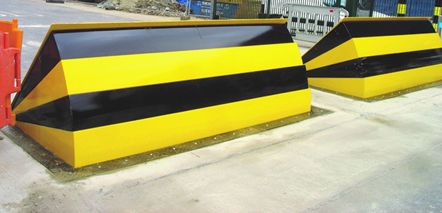
14 and the surface 12 to which the barrier 10 is protected might be made from concrete - Wedge Barriers. 2, the barrier 10 is mounted to or consists of an anchor or subframe (e. g., support 30 shown in FIG. 2 )protected under the surface 12. The bather 10 might be bolted to the support or safeguarded to the anchor by various other mechanical bolts. In the detailed embodiment, the obstacle 10 includes a wedge plate 16, that includes a section that is significantly parallel with the surface 12 when the barrier 10 is in the withdrawed placement. To put it simply, cars or individuals might overlook the obstacle 10 when the barrier 10 is in the withdrawed placement and experience minor altitude about the surface 12 while on the obstacle 10. As talked about thoroughly listed below, when the barrier 10 remains in the deployed placement, the wedge plate 16 is held and sustained in a raised placement by a lifting mechanism of the barrier 10. Furthermore, the components 18 may be bolted or otherwise mechanically coupled to one another. In this manner, repair work or replacement of several elements 18 may be simplified and streamlined. That is, repair service or substitute of single elements
18 might be done faster, quickly, and price properly. FIG. In particular personifications, the support 30 might be a steel structure including plates, beam of lights(e. g., I-beams ), and/or various other structures that are safeguarded within the foundation 14, which may be concrete. At the surface 12, a top side 28 of the support 30 might be at least partially subjected
, consequently making it possible for the attachment of the obstacle 10 to the anchor 30. g., threaded openings)in several beam of lights or plates of the anchor 30 may be subjected to the surface area 12. In this way, screws 32 or various other mechanical my website bolts may be used to secure the obstacle 10 to the support 30. As the obstacle 10 is placed to the surface 12 of the structure 14, collection of debris and various other material below the obstacle may be minimized, and elements of the bather 10 might not be subjected to below quality environments. As shown by reference numeral 52, the training mechanism 50 consists of components got rid of underneath the wedge plate 16. For instance, the components 52 underneath the wedge plate 16 might include an electromechanical actuator, a webcam, several cam surfaces, etc. In addition, the training mechanism 50 includes a spring setting up 54
The springtime rod 58 is combined to a cam(e. g., web cam 80 revealed in FIG. 4) of the lifting device 50. The springs 60 disposed regarding the springtime pole 58 are kept in compression by springtime supports 62, consisting of a dealt with springtime assistance 64. That is, the set spring assistance 64 is repaired about the structure 14 and the rest of the bather 10.
The smart Trick of Wedge Barriers That Nobody is Talking About
g., springtime support 65 )may be fixed to completion of the spring pole 58 to enable compression of the springtimes 60. As the springs 60 are compressed in between the spring supports 62, the link springtime assembly 54 creates a pressure acting on the web cam coupled to the spring rod 58 in a direction 66. The remaining force applied to
the cam web cam deploy the wedge plate 16 may be provided given an electromechanical actuator 84 or other various other. The springtime setting up 54 and the actuator 84(e. g., electromechanical actuator)may run with each other to convert the web cam and raise the wedge plate 16.
As mentioned above, in the deployed setting, the wedge plate 16 serves to block accessibility or traveling beyond the obstacle 10. The barrier 10(e. g., the wedge plate 16 )may obstruct pedestrians or automobiles from accessing a home or pathway. If an automobile is taking a trip towards the released wedge plate 16(e. For instance, in one circumstance, click this site the safety legs 86 might be expanded throughoutmaintenance of the barrier 10.